There is little doubt that the internet of things (IoT) is well on its way to transforming how we live, work and do business. Power over Ethernet (PoE) applications are rampant, delivering low power and low cost to the commercial side in such products as IP phones, cameras and card readers. PoE for the IoT is becoming more important in the industrial realm as well, providing operational efficiency, intelligence, asset management, easy maintenance and greater opportunities in automation. Yet, one industrial segment has been pretty much shut out of PoE’s advantages — the industrial harsh environment.

PoE delivers data and power via a single Ethernet cable. Ethernet has up to one hundred times the data throughput rates compared to fieldbus, is similar in cost with analog interfaces and is compatible with existing automation solutions. PoE in harsh environments is fairly new and adoption is slowed by two things: excessive, damaging heat and the lack of standards.
How Harsh is Harsh?
One of the major differences between a commercial environment and a harsh environment is the ambient temperature and the ability to control the environment. In a harsh setting, large fluctuations in temperature are often normal. Attributes of a harsh environment include:
- High ambient temperatures
- Exposure to chemicals, flux and weld spatter
- Cables subject to damage, from abrasion to being stepped on
- Cable applications in which the environment is not controlled
Also important is what contributes to a substantial rise in cable temperature. Included are:
- Bundle size
- Power source
- Ambient air temperature
- Application and environmental conditions
- Type of pathways
- Number of energized conductors or pairs
- Cable construction
- Resistance in copper
- Adding current
As cable temperatures rise, so do problems. For example, insertion loss increases, which leads to bit errors and retransmits. When cables are heated, the conductive properties of copper change so that DC resistance increases with temperature — an important factor that must be considered in cable choice. Cable heating in bundles is also problematic. When multiple cables are bundled, central cables can’t dissipate heat. This is even more of a concern in warm installation environments. When cable temperature ratings are exceeded, cables can be physically damaged. In this environment, stranded wire is typically used to handle the challenges of vibration and durability in industrial applications. Most PoE standards are written around solid conductor cable. While a look at standards is important, PoE is rapidly moving into non-standard applications with higher power capabilities, expanding what was previously possible.
A Look at Standards Governing PoE Cable
PoE is used in a variety of commercial applications, but its expansion into industrial harsh environments is a relatively new endeavor. Unfortunately, the standards that were in place didn’t go far enough or develop fast enough for use in harsh environments.
TIA TSB-184-A — Guidelines for supporting power delivery over balanced twisted-pair cabling
- Recommends no more than 15° C rise in temperature at ambient temperature of 45° C
- Based on typical category cable temperature rating of 60° C
- Testing performed in standardized bundles of 100 cables
ISO/IEC TR-29125 and CENELEC TR 50174-99-1 — International cabling guidelines for PoE++.
ANSI/TIA-568-C.2 specifies the electrical parameters for Cat 5e, Cat 6 and Cat 6a structured cabling channels. The maximum total length of these channels is 100 m.
IEC 60512-99-002 covers connectivity engaging or disengaging PoE.
IEEE 802.3af PoE ensures reliable operation in any configuration that would be possible with regular Ethernet. It targets network devices that require approximately 13 W of electrical power. It is possible for network cable and connectors to handle more power, but high-power PoE systems are often not backwards compatible with regular 802.3af PoE.
IEEE 802.3at, or PoE Plus (PoE+)
- PoE Plus nearly doubles the amount of electrical power available to powered devices to 25.5 watts.
- PoE Plus recognizes 802.3af powered devices. PoE Plus-powered devices can also be connected to 802.3af PoE switches or injectors to restrict how much power they use.
- 802.3at includes scope for power sources and powered devices to communicate with each other to negotiate an allowance of electrical power.
IEEE 802.3bt Type 3 and Type 4
The new standard, PoE++ (4PPoE) IEEE 802.3bt Type 3 and Type 4 features maximum current of 600 mA and 960 mA, respectively, with power at the source (PSE) of 60 W and 99 W, with power at the device (PD) of 51 W and 71 W and a maximum data rate of 10GBASE-T. With power on all four pairs, there is a 50 percent current increase; double the number of pairs and get a triple increase in power over the existing IEEE 8023at.
The new 4PPoE standard requires four-pair CAT5e or higher. While it will run on CAT5e, CAT6A improves thermals and power efficiency.
The new IEEE 802.3bt standard increases the maximum PoE power available mainly by using all four pairs of the structured wiring. IEEE 802.3bt extends power classification information for meaningful power management, enabling support of multiple PoE classes while being backwards compatible.
Underwriters Laboratories LP Certification
Underwriters Laboratories (UL) performed a commissioned study regarding possible safety issues created with the transmission of power with communications cabling. The study focused on power in volts, watts and in amps, rather than on applications.
As a result of the study, UL introduced a Limited Power (LP) Certification to simplify cable choice for PoE applications. The LP certification indicates that a cable is tested to carry PoE under worst-case installation scenarios without exceeding the temperature ratings and accounts for large bundle sizes, high ambient temperatures and other environmental effects.
The certification provides an easy way to ensure that installations are ready for increasing power levels and are not susceptible to safety issues caused by excessive heat generation. This simplifies installation planning and provides a consistent test method for evaluating a cable’s ability to handle a specified current. Certified cables carry the UL Mark, ensuring compliance and reducing risk. Additionally, test-based requirements allow for innovation in cable design. As explained in the following paragraph, LP rating is not required to use PoE.
2017 National Electric Code
The 2017 National Electric Code (NEC) imposes new requirements on cables running high power levels of the next-generation PoE standard. NEC recognizes the new UL LP listing. The 2017 NEC is focused on the overall bundling sizes of cables running high PoE power levels and applies only to cables that are permanently installed.
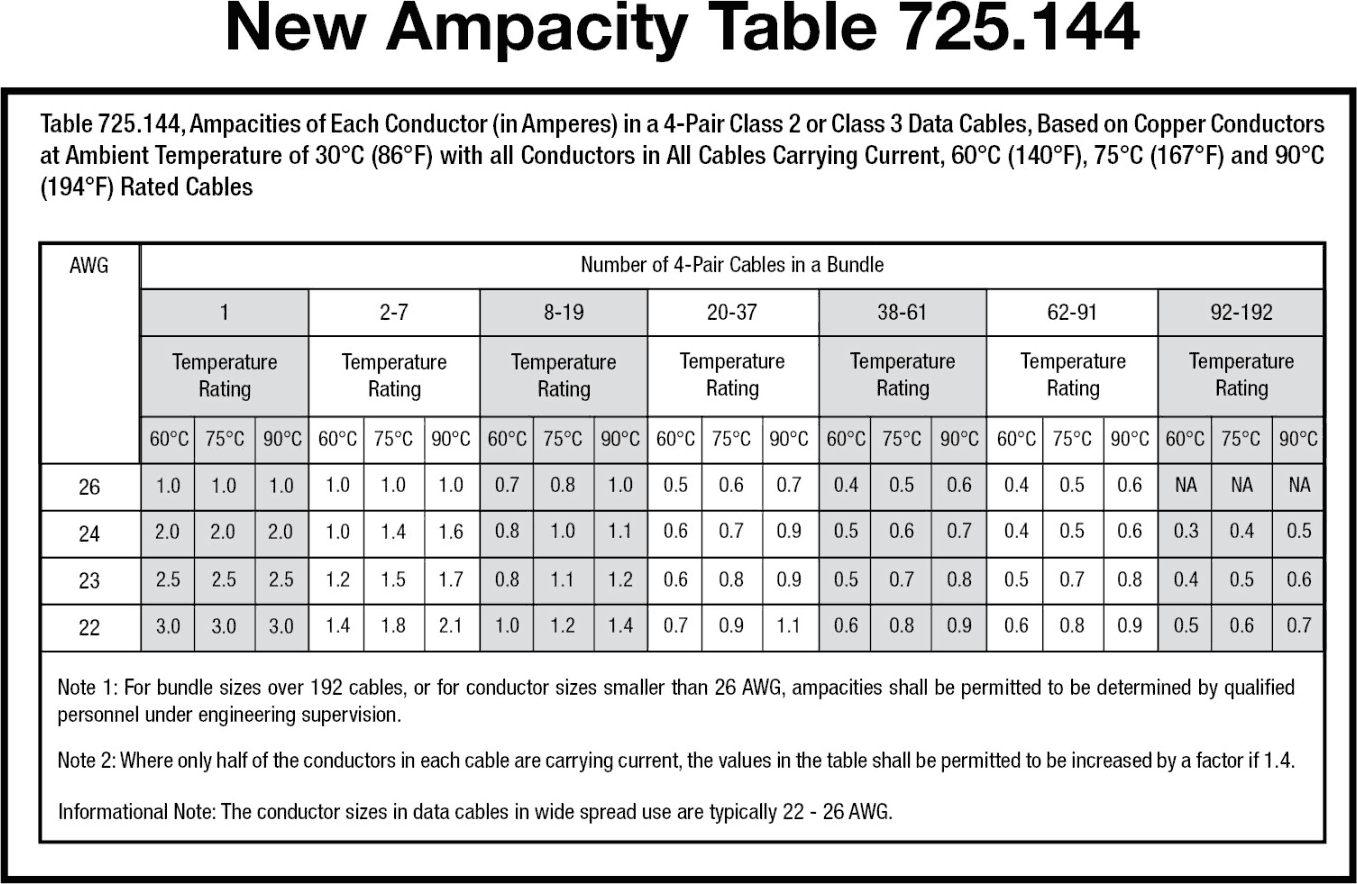
The NEC 2017 edition contains new requirements that address heat rise when power is greater than 60 W (Type 3) and includes ampacity tables (see Table 1), specifying the maximum ampacity allowed for a certain cable bundle size, conductor gauge and cable temperature rating installed in an ambient temperature of 30° C (86° F). Complying with these ampacity tables is required, however the use of an LP-certified cable as an alternative to following the ampacity table is allowed.
What is still missing for designers, however, is the guidance that already exists for long-standing commercial applications. Now, Quabbin has developed a Matrix that will simplify selection.
Quabbin: Making Single-Cable PoE for Harsh Environments an Easy Choice
The reality is, harsh environments expose cables to elements not present in typical PoE-based application in commercial cabling locations. Bringing that commercial solution into a harsh environment will result in cable degradation, electrical failures and even safety hazards.
Instead, consider a cable that is created specifically for the application. Not only does Quabbin have a broad range of harsh-environment specific cables, it delivers test data and reports that support the functional abilities of Quabbin cables.
At Quabbin, the goal is to make translation, selection and design options clear and useful to the design engineer. For that reason, Quabbin has created a series of cables that specifically deliver what is required for use in a harsh environment. Additional tools make selection that much easier. These tools range from an online cable finder to Quabbin’s Matrix that acts as a guide to select the cable specific to the application. Using the Matrix is simple after reviewing the impact of temperature, DC resistance (DCR) and insertion loss.
The Quabbin Product Matrix
| Popular Quabbin products (part #) | 5030 5031 5032 |
5730 5731 5732 |
5023 5025 5027 5028 |
5750 5751 5752 5753 |
5924 | 5800 5801 5802 |
|
| Cable specifications | Wire size (AWG) | 26 | 26 | 24 | 24 | 22 | 22 |
| Pair count | 2 | 4 | 2 | 4 | 2 | 4 | |
| Ambient temp. (°C) | 20 | 20 | 20 | 20 | 20 | 20 | |
| Cable temp. rating (°C) | 75 | 75 | 75 | 75 | 75 | 75 | |
| DCR (LOOP) per meter | 0.278 | 0.278 | 0.172 | 0.172 | 0.12 | 0.12 | |
| Max. distance (m) | 50 | 50 | 72.6 | 72.6 | 100 | 100 | |
| Max. bundle size at 0.5 A per wire or 1 A per pair (Type 4) per NEC 2017 | n/a (4) | 91 | n/a (4) | 91 | n/a (4) | 192 | |
| Voltage drop per meter | PoE IEEE 802.3at Type 1 (350 mA, 15.4 W) | 0.0973 | 0.0973 | 0.0602 | 0.0602 | 0.042 | 0.042 |
| PoE + IEEE 802.3at Type 2 (600 mA, 30 W) | 0.1668 | 0.1668 | 0.1032 | 0.1032 | 0.072 | 0.072 | |
| 4PPoE 802.3bt Type 3 (600 ma per pair, 60 W) | 0.1668 | 0.1668 | 0.1032 | 0.1032 | 0.072 | 0.072 | |
| 802.3bt Type 4 (960 mA per pair, 100 W) | n/a (4) | 0.26688 | n/a (4) | 0.16512 | n/a (4) | 0.1152 | |
| Supported modes (1, 2, 3) | Mode A | Mode A Mode B 4 pair mode |
Mode A | Mode A Mode B 4 pair mode |
Mode A | Mode A Mode B 4 pair mode |
|
Notes to Matrix
- Mode A uses pair two (orange in QWC cables) and pair three (green) so it can be used with two pair cables.
- Mode B uses pair one (blue in QWC cables) and pair four (brown) so it cannot be used with two pair.
- Standards compliant devices will determine which mode can be used.
- Two pair cables cannot support Type 4 and therefore the bundle size is not restricted by the NEC.
Temperature
In harsh environments, ambient temperature can have a great impact. The temperature ratings of the cable are based on the aging of the plastic. Higher temperatures degrade the plastic faster, causing it to lose tensile strength or elongation. At higher temperatures, the maximum length of the cable run will typically decrease. Temperature ratings on the cables referenced in the Matrix are higher. Although the cable is capable of carrying more current than the standard, it is imperative that a connector be used with a rating for that current. The ability to use cables with high temperature ratings, so that cables stay below their maximum temperature ratings, is key to cable safety. Quabbin cables in the 75° C are available.
DC Resistance
In commercial channels, cables are typically 24 and 23 AWG horizontal, and 24 and 26 AWG for patch cable gauge. In harsh environments, it is common to find 26, 24 and or 22-gauge stranded wire used for a channel, therefore DC resistance (DCR) represents a major challenge since most cable providers do not specify the DCR of their cables. Designers, however, need to know what the DCR is so that calculations are accurate. While DCR unbalance is seldom an issue in high-quality cables with a high-temperature rating or LP certification, cables that have poor workmanship will cause resistance unbalance. This is more critical when power increases and when the number of PoE devices continues to rise.
DCR is determined by the cross-sectional area of the copper conductor and the conductivity of the copper. The values included in the Matrix are industry-accepted values for both. Quabbin includes this information on each cable.
Insertion Loss
It is easy to forget that the cable is not just carrying power, it is carrying data. When the temperature is too hot, or the cable distance is challenging, data will stop working. With some cables and some data protocols it isn’t an issue, but at the extreme ends of distance and data rates, it is.
Stranded patch cable insertion loss is de-rated compared to horizontal cable insertion loss by 20 percent for 24 AWG and by 50 percent for 26 AWG. It is important to note that standard channel insertion loss is based on 24 AWG patch cables for Cat 5e and Cat 6 and 26 AWG patch cables for Cat 6a. 26 AWG can be used in Cat 5e and Cat 6 and 24 AWG can be used in Cat 6a, but the cable length is calculated differently.
Derating insertion loss with temperature can be accomplished by using calculations in Annex G of ANSI/TIA-568-C.2 as guidance. These calculations are for commercial cables that have construction and material differences when compared with harsh-environment cables. Quabbin is currently studying harsh environment cable performance at elevated temperatures. The results of this study will be the subject of a future white paper.
Quabbin Cable Solutions
Two cables in the harsh-environment line include:
DataMaxExtreme Industrial Ethernet Cat 5e/ 22 AWG — Unshielded
.png)
DataMax Extreme Industrial Ethernet Cat 6/6a/24 AWG — Shield & Braid
.png)
Summary
PoE delivers power and communication to applications where harsh conditions are the norm, providing tools to convert from traditional wiring to PoE for industrial IoT adoption. Customers that may plan to run PoE above 60 W might be unclear as to how to translate commercial PoE to the industrial or harsh environment segment, but Quabbin can help.
Getting started with implementing PoE in a harsh environment application is now much easier. It begins by evaluating the application’s primary constraints: environmental challenges, especially temperature, length of cable run, and cable materials and type.
Quabbin provides many online tools and resources to help customers find the right product and engineering expertise. Contact Quabbin today for in-depth assistance with harsh environment cable challenges.